PDF Download
Fiberesin’s “Made In America” Production Supports COVID-19 Relief Loans
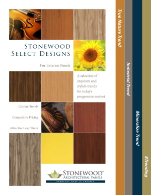
Commitment
All of Fiberesin’s product lines, including Stonewood Architectural Panels, are made in Oconomowoc, Wisconsin.
Paycheck Protection Program (PPP) and/or Economic Injury Disaster Loan (EIDL) recipients are required to purchase American made products when possible.
Federal guidelines for PPP and EDIL
As construction projects around the country begin to resume in various capacities, businesses will be re-evaluating their supply chain for goods and services in order to move projects ahead. For some, that will include moving forward with the assistance of the Paycheck Protection Program (PPP) and/or Economic Injury Disaster Loans (EIDL). These loans have an American Made Commitment. Business owners utilizing these loans must certify that, "To the extent possible, [they] will purchase only American-made equipment and products."
Fiberesin would like you to know that all of our products are domestically produced in America’s heartland. Because of the wide range of products we manufacture for the construction industry and the healthcare industry, Fiberesin is considered an “Essential Business” by the State of Wisconsin and has remained fully operational during the crisis. Most of our products are available at or below our standard quoted lead times.
The American Advantage
What does domestic production mean for you? With our American-made commitment, Fiberesin and its brands, Stonewood Architectural Panels and Edgemold, are able to offer accelerated lead times, and exceptional customer service from a team of highly-trained essential workers who are here to guide you through unprecedented business demands. Customized orders, unique delivery requirements, specifications, engineering—our operations in Oconomowoc and Ashippun, Wisconsin are able to offer solutions for every aspect of your project.
Durable Against COVID-19 Sanitation
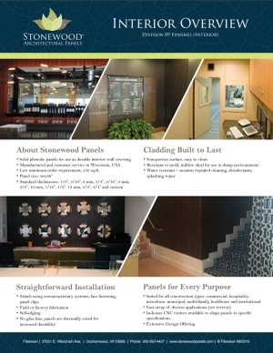
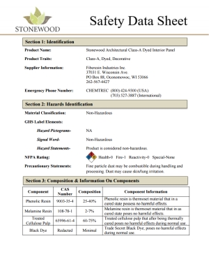
Our interior line of Stonewood (solid phenolic) products are chemical-resistant products. This means that they meet the Scientific Equipment and Furniture Association—SEFA 8 Standard—for chemical resistance/cleanability. These materials have immediate applications as a component or finished product in medical, laboratory, hospitality or food settings. They can be repeatedly cleaned and sanitized against Covid-19 with all approved disinfectants and sanitizers as outlined by the CDC.
Ready For Mobilization
Fiberesin Industries’ product lines including Stonewood Architectural Panels, Edgemold tables and Stonewood components, are ready for immediate mobilization and delivery to ensure your project is completed. Contact us with your drawings and specifications. The products are made-to-order in Wisconsin, with average lead time 3-5 weeks. Accelerated lead times for Covid-19 essential goods are available upon request, please contact us.
Daily Operations
As always, we are committed to the health and safety of our staff and customers. We continue to maintain the highest product and manufacturing sanitation measures, as well as staying in full compliance with the guidelines outlined by the State of Wisconsin for essential businesses operations. The safety of our workers remains our top priority.
PDF Download
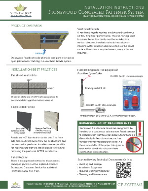
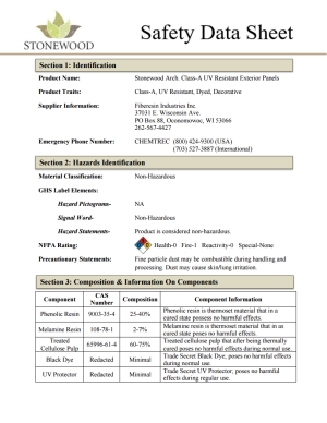
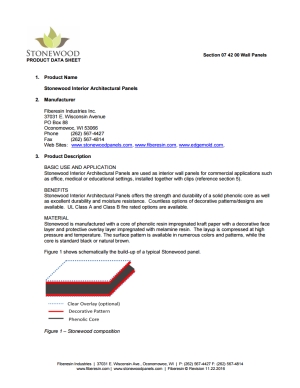
PRODUCT OVERVIEW
|
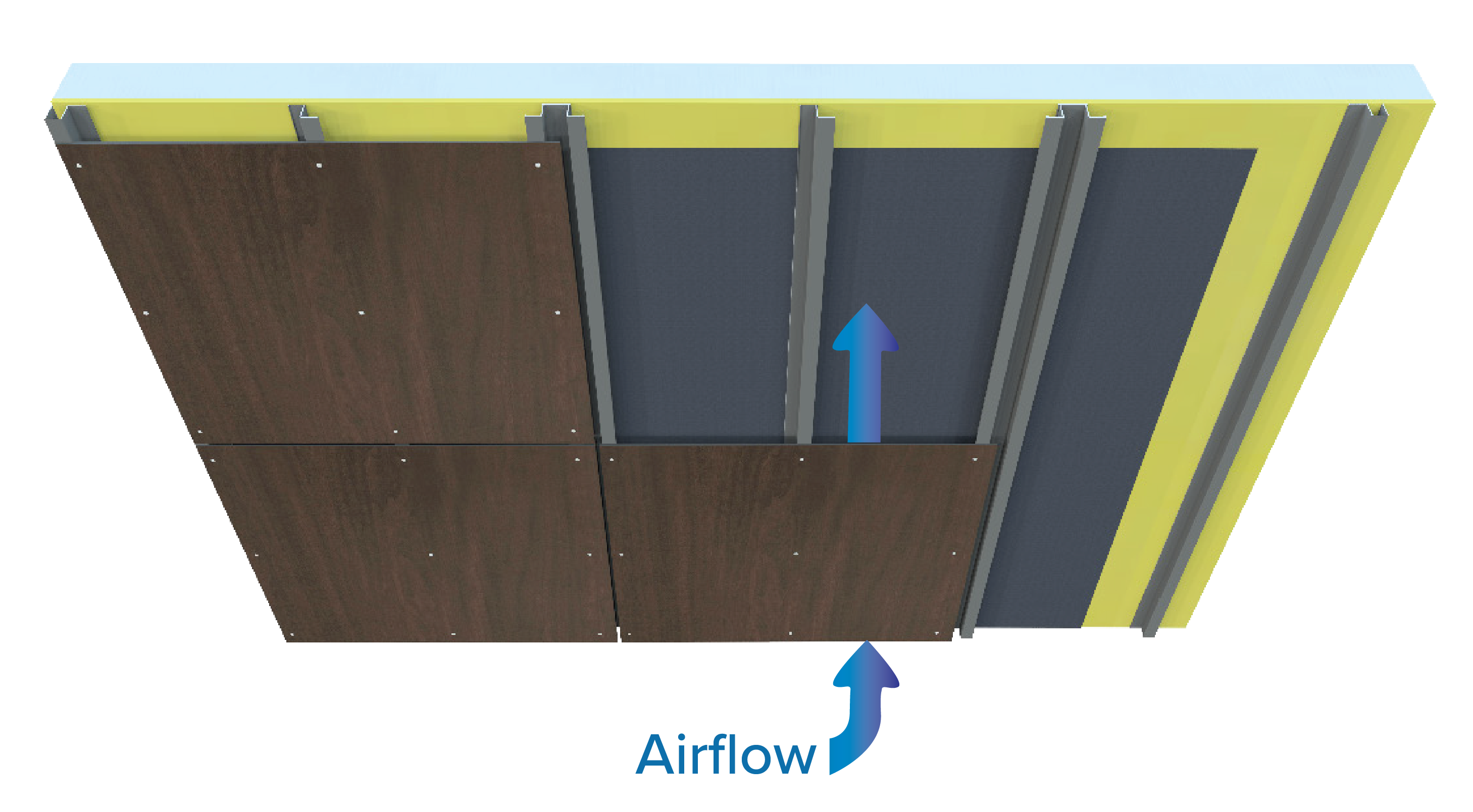
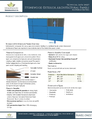
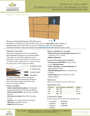
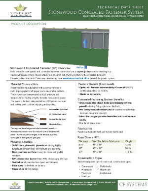
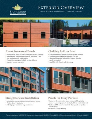
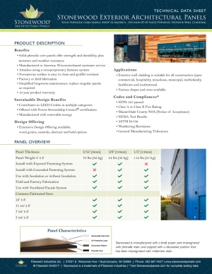
Stonewood panels are solid phenolic core panels for use as open joint exterior cladding in a ventilated system.
|
Ventilated Facade
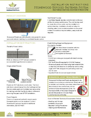
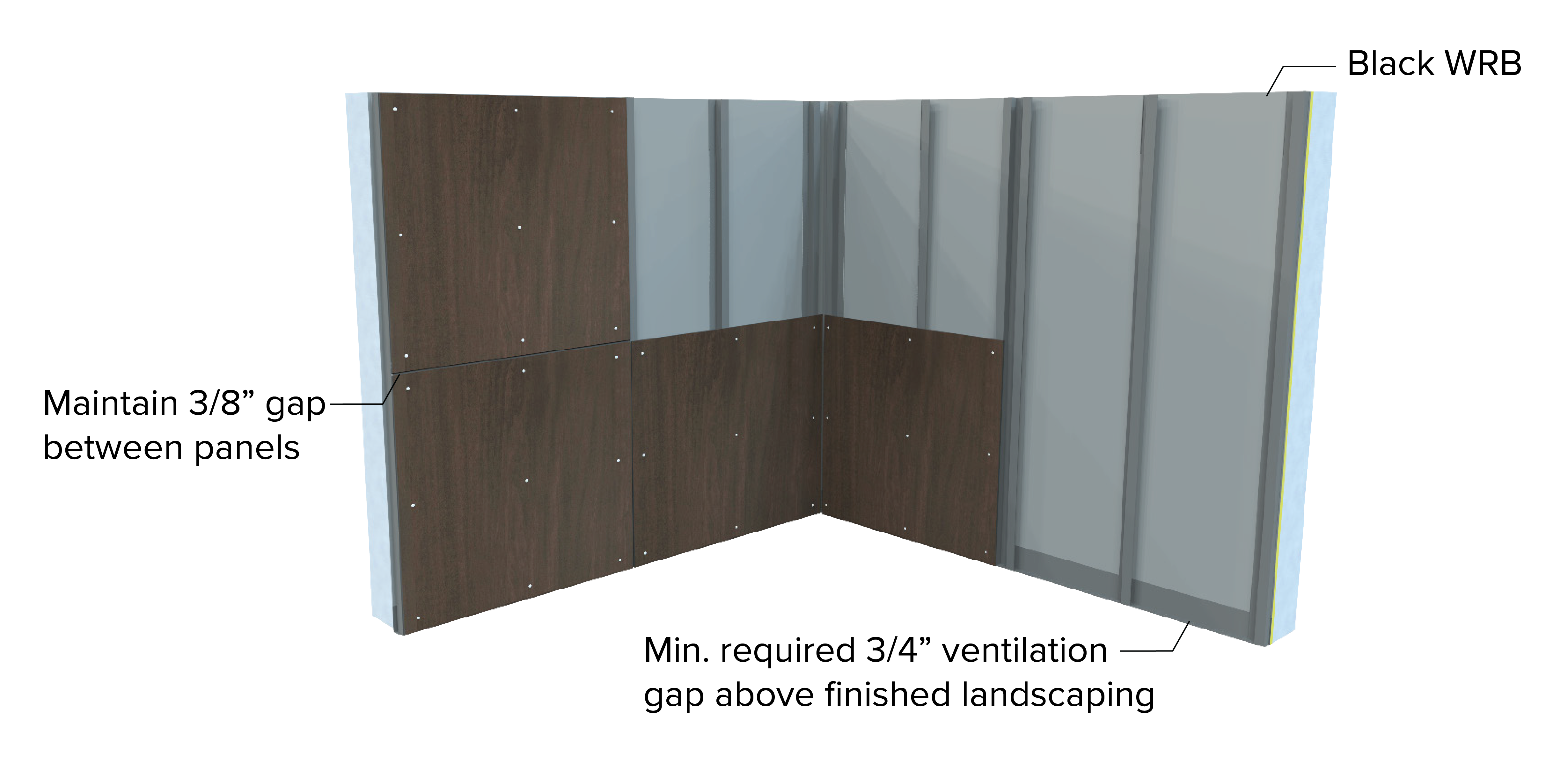
A ventilated façade requires unobstructed continuous air flow for proper performance. The sub-framing used to create the air flow cavity must be installed in a vertical direction. Installation should not allow for standing water to accumulate anywhere on the panel surface. If conditions require battens, weep holes are required.
|
Installation Best Practices
|
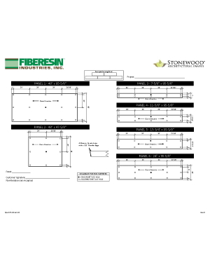
Panel to Panel Joints
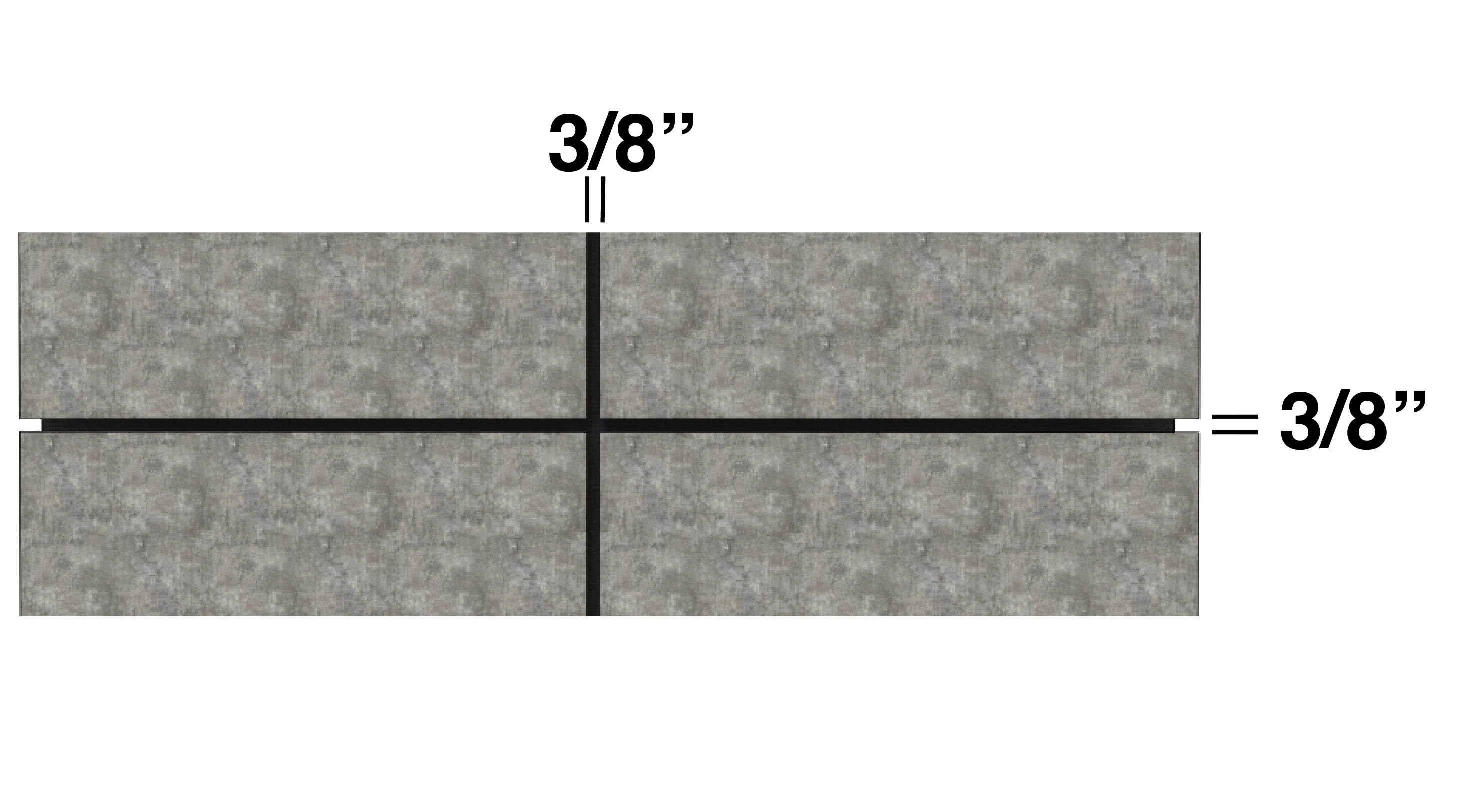
Minimum distance of 3/8” between panels to minimum distance of 3/8” between panels toaccommodate hygrothermal movement.
|

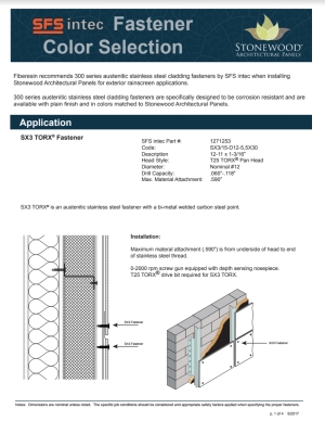
Field Drilling Required Equipment
Specs
Olsa Tools Torque Screwdriver with Hex head and T-handle, 10-50 in-lb, +/-6% accuracy or equivalent (not supplied by Fiberesin).
- 0-2000 rpm screw gun equipped with depth sensing nosepiece.
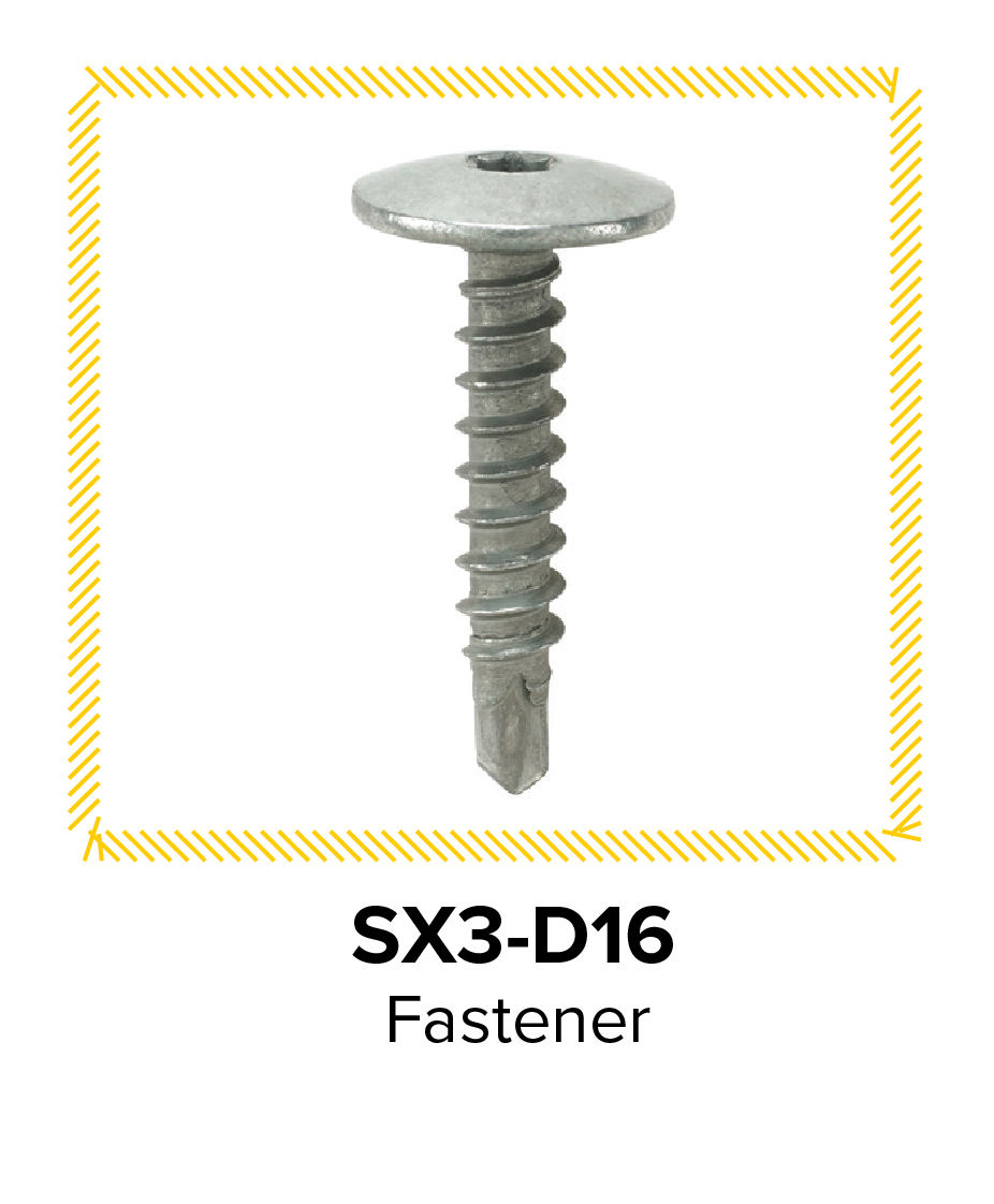
- T25 Torx® Drive Bit required for SX3-D16 Fastener.
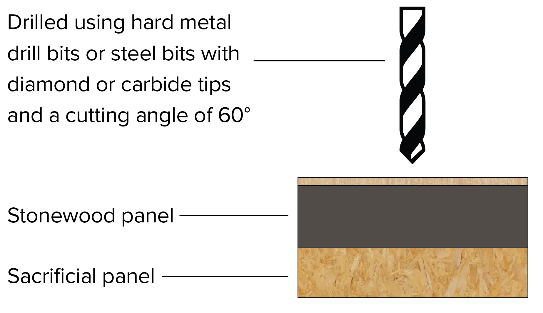
- Stonewood panels are drilled using hard metal drill bits or steel bits with diamond or carbide tips and a cutting angle of 60°. Bits designed for perforating metal may also be used.
- Important Note: Do not use impact drivers
|
|
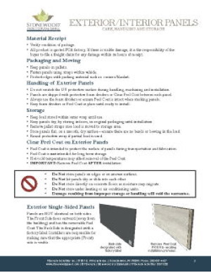
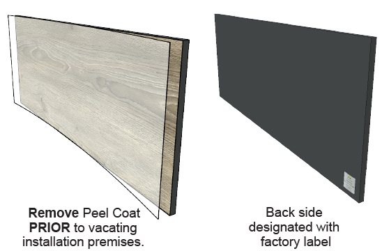
Single-sided Panels
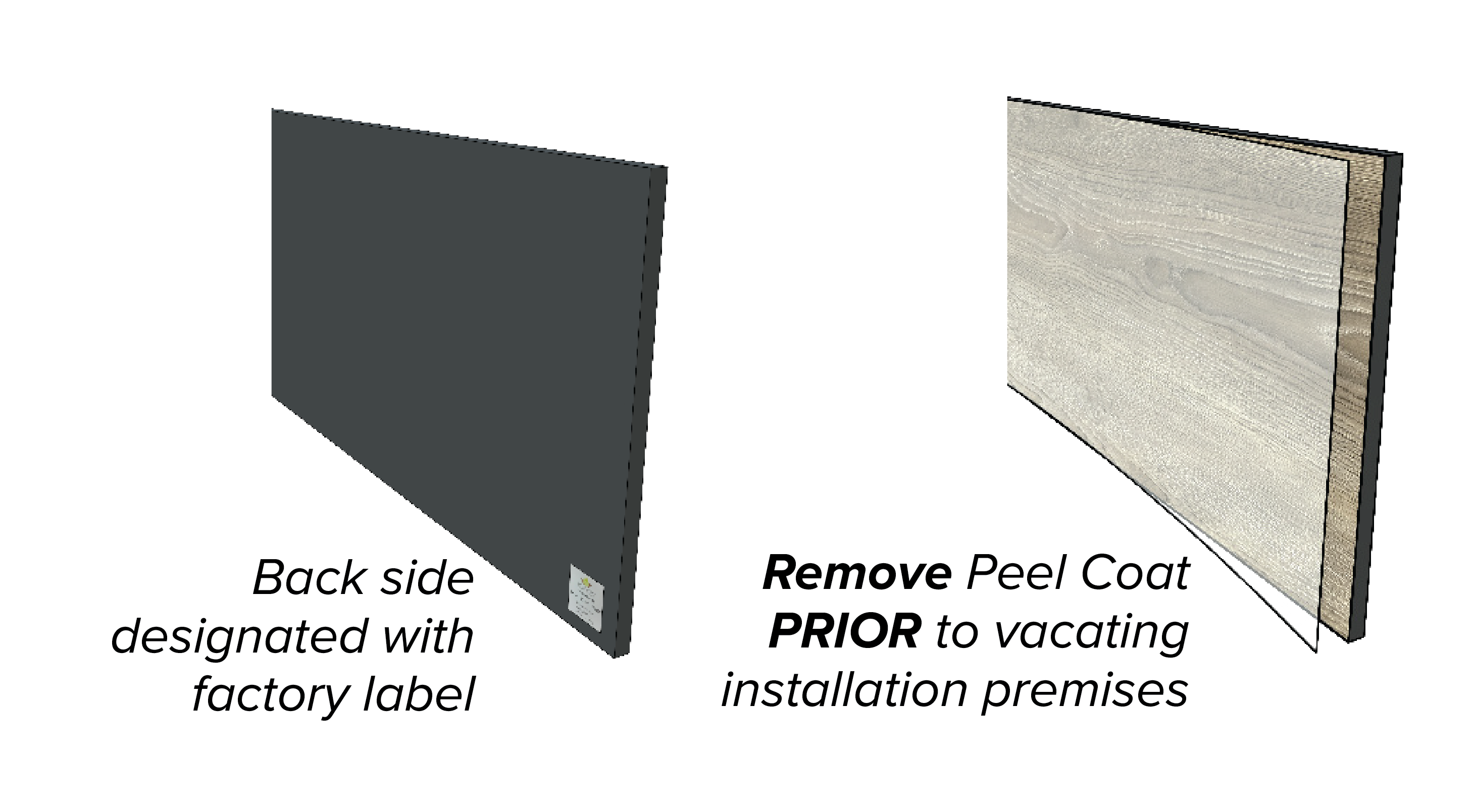
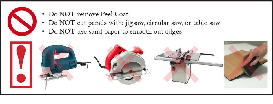
Panels are NOT identical on both sides. The front side faces outward (away from the building) and has the removable peel coat. Installers are responsible for making sure that the (front) side is visible and removing the peel coat AFTER installation.
|
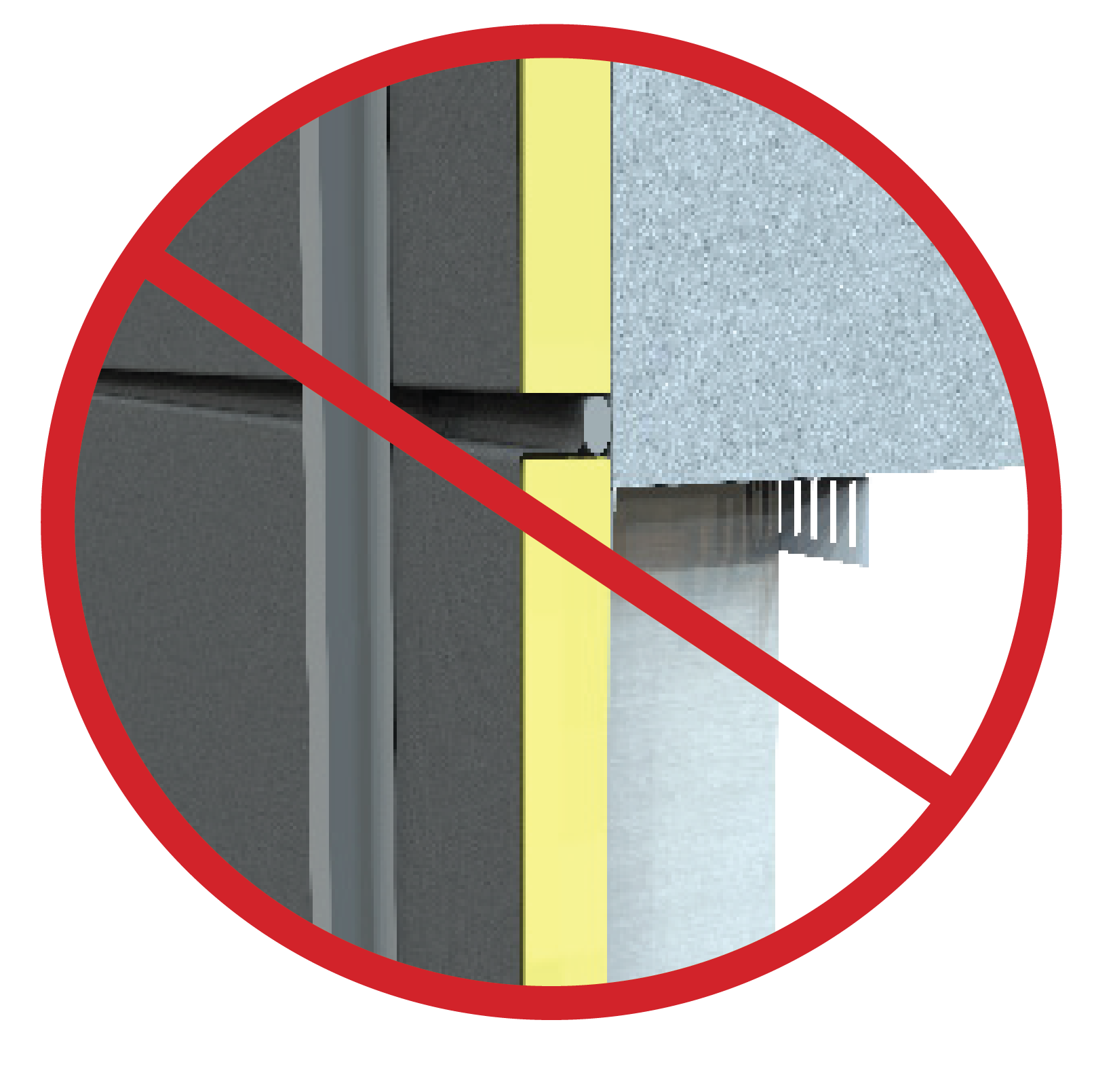
Expansion Joint Requirements
Stonewood Architectural Panels are designed to be installed on a continuous substructure. Panels are not to be installed such that they span areas where there is a discontinuity in the substructure, such as vertical or horizontal expansion joints. It is the responsibility of the project designer to ensure that panels do not span these substructure discontinuities.
|
|
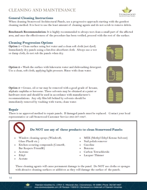
Panel Repairs
There is no approved method to repair panels. Damaged panels must be replaced. Contact Stonewood Customer Service for additional information, 262-567-4427.
|
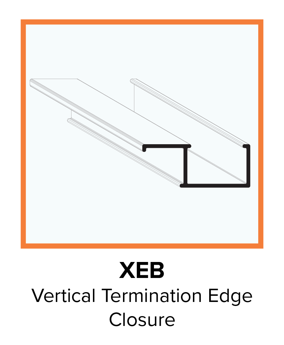
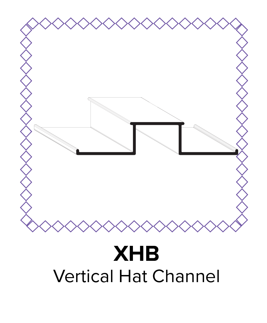
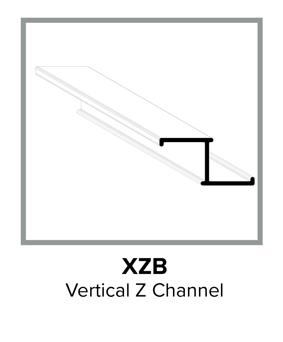
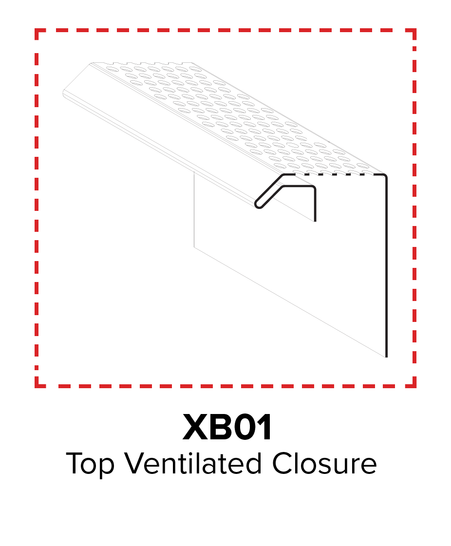
Parts Placement Overview
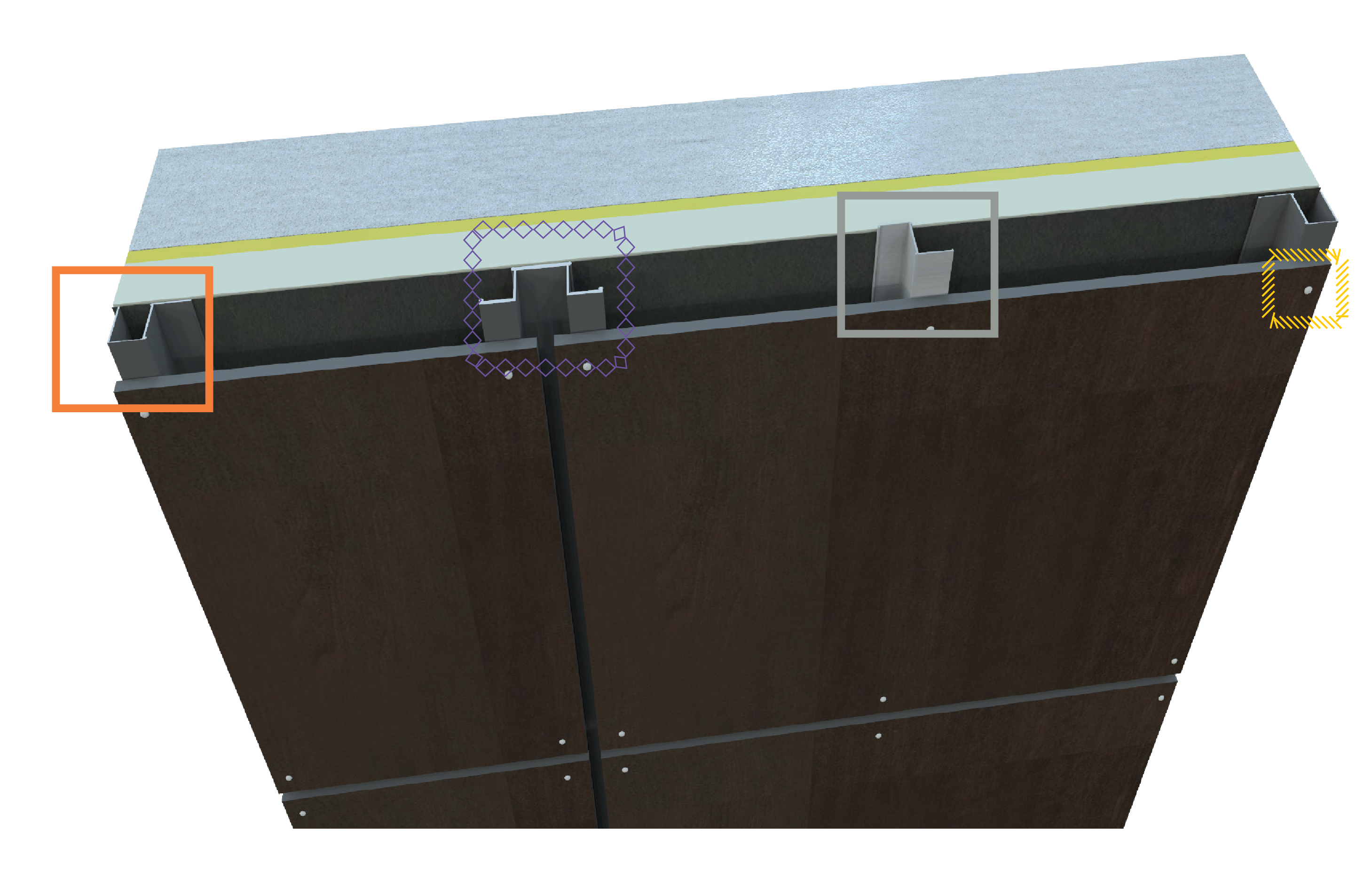
Parts Overview
Step 1
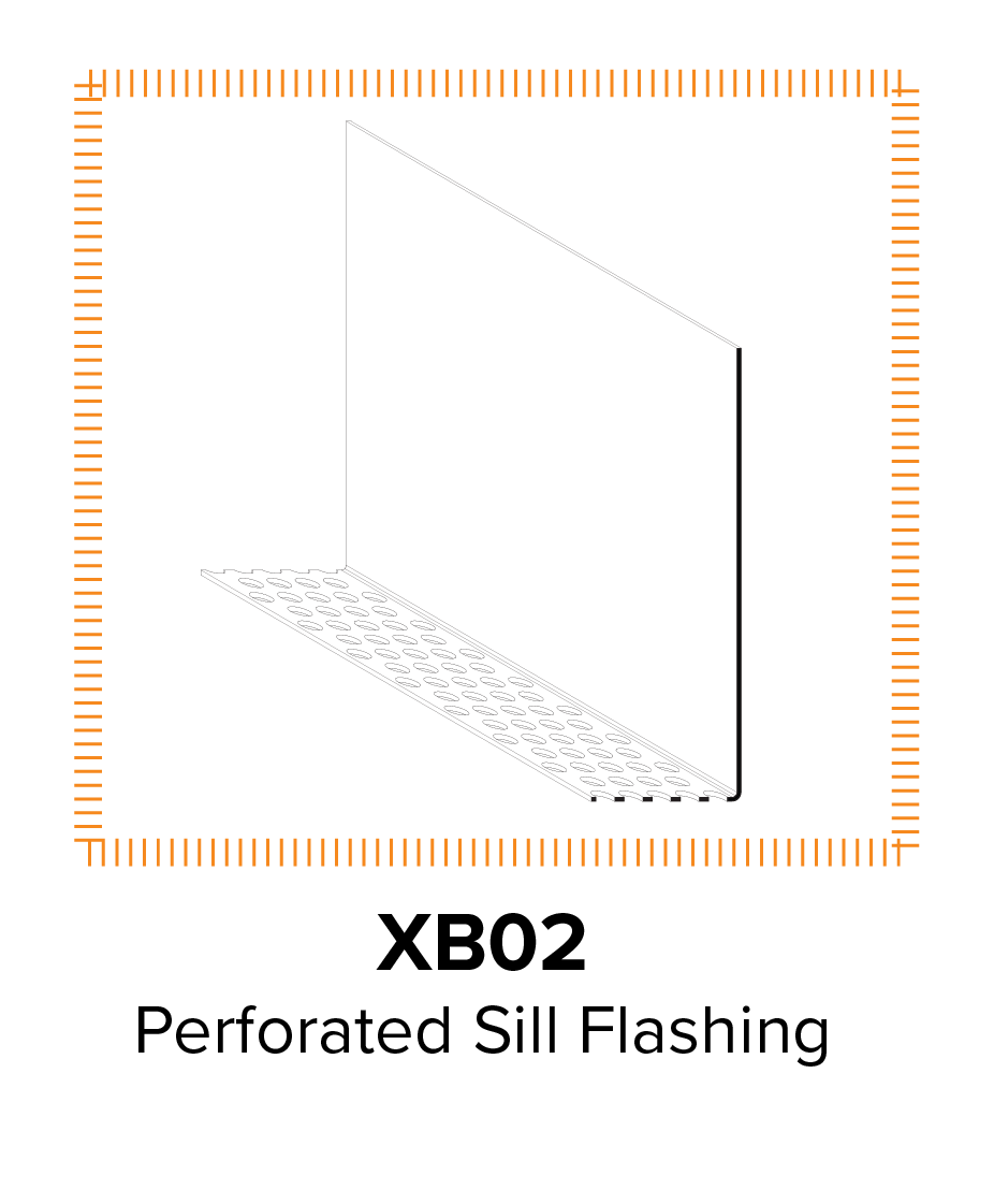
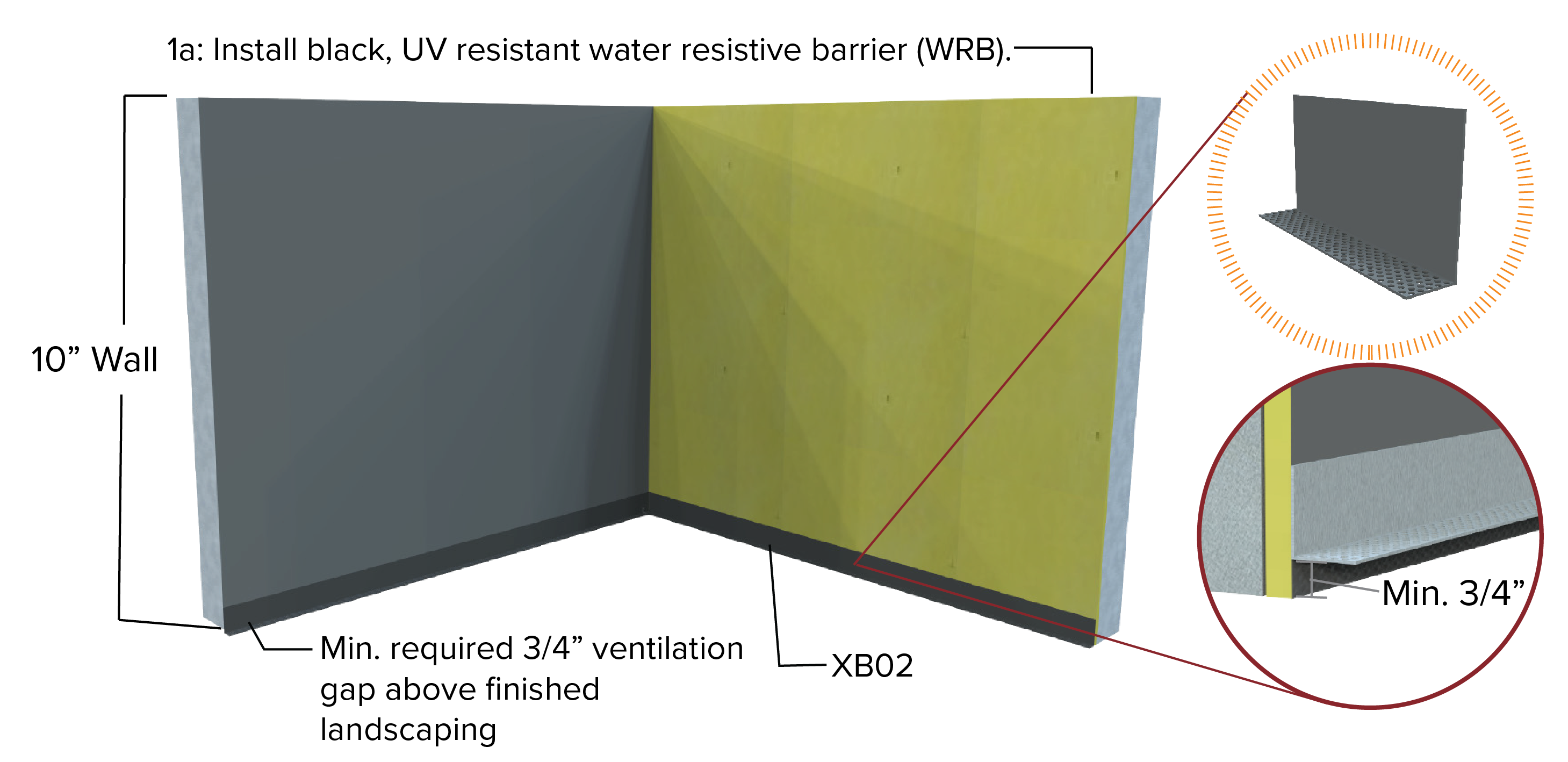
1b. Use laser level to ensure XB02 is LEVEL and FLUSH.
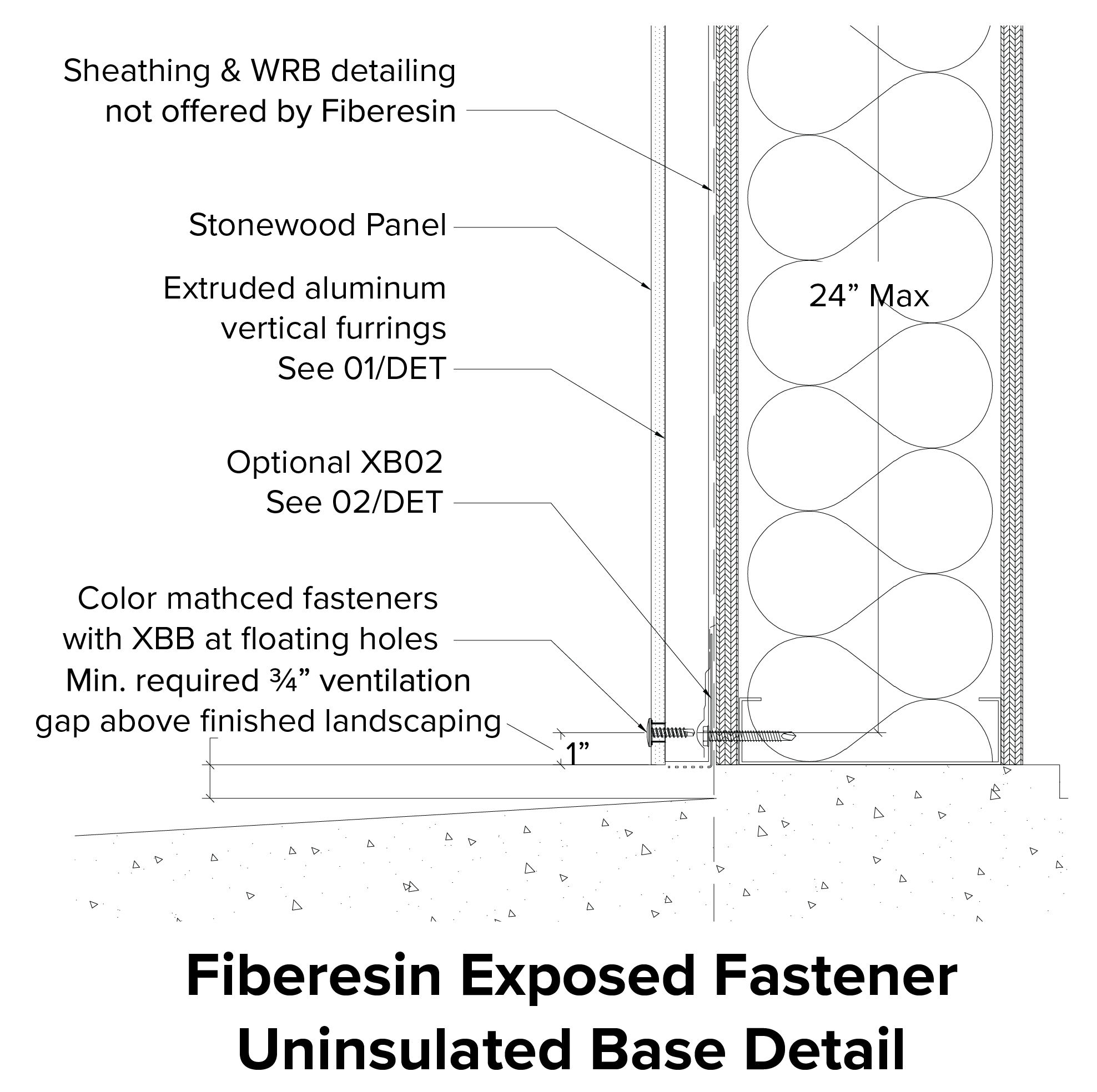
1c. Starting at the bottom of the wall install XB02 a minimum of ¾” ABOVE the finished landscaping, to ensure the required unobstructed air flow behind the panels.
Step 2: Rail Placement
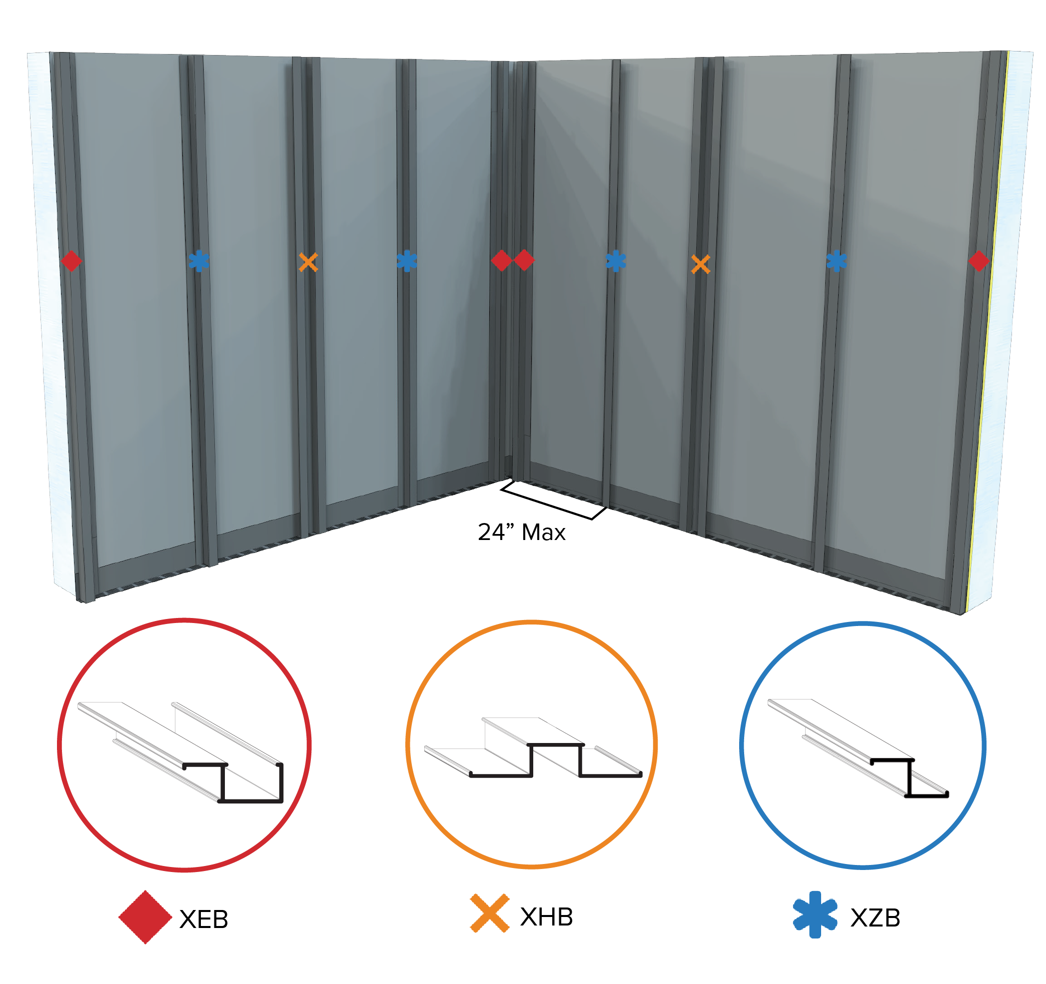
2a. Rails must be placed a maximum of 24" on center horizontally.
Step 3: Prep Stage
|
Field Drilling Required Equipment
Provided by Installer
Olsa Tools Torque Screwdriver with Hex head and T-handle, 10-50 in-lb, +/-6% accuracy or equivalent (not supplied by Fiberesin).
Equipment Specs
- 0-2000 rpm screw gun equipped with depth sensing nosepiece.
- T25 Torx® Drive Bit required for SX3-D16 Fastener.
- Stonewood panels are drilled using hard metal drill bits or steel bits with diamond or carbide tips and a cutting angle of 60°. Bits designed for perforating metal may also be used.
|
Fixed and Floating Point Pre-Drilling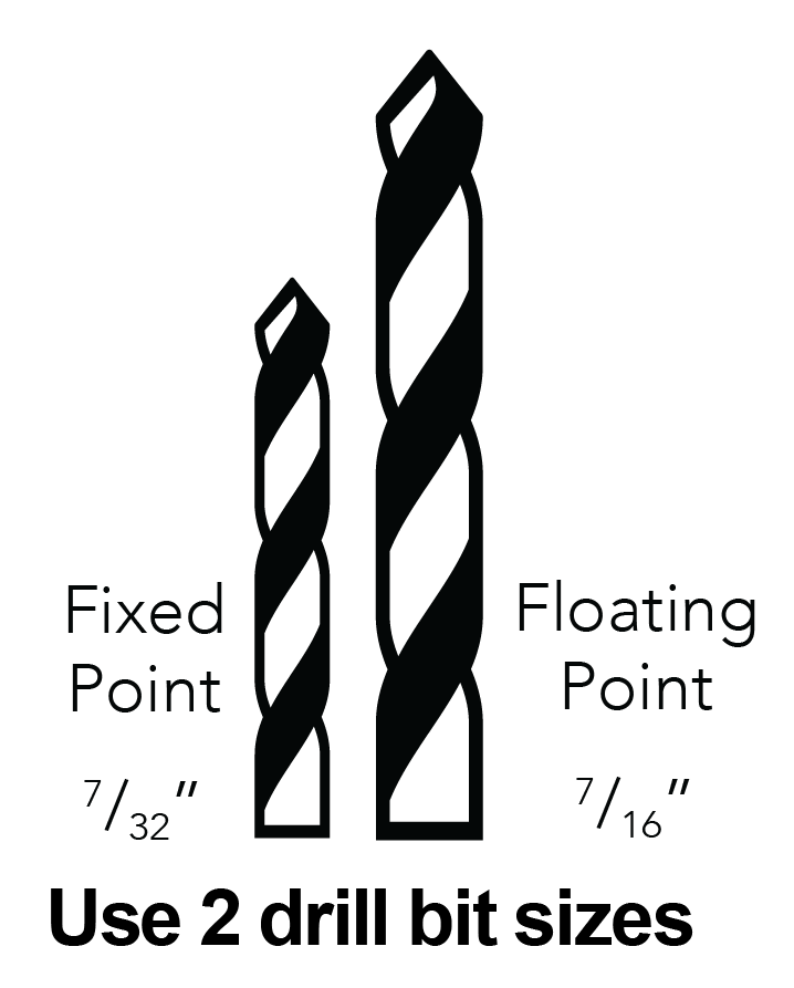
The fixed point (as close as possible to geometric center) is permanently fixed and is the same size as the screw thread width. There is one fixed point per panel. The fixed point ensures the panel movement is evenly distributed. The remaining holes must be fabricated as floating points.
|
|
Important Note
Do not use impact drivers!
|
|
Field Drilling
Stonewood panels are drilled using hard metal drill bits or steel bits with diamond or carbide tips and a cutting angle of 60°. Bits designed for perforating metal may also be used.
- Supporting sheets (plywood, chipboard) must be used under the panel to ensure clean hole and eliminate “breakout.”
- To avoid breakout, the feed speed of the drill head and pressure applied should be gradually reduced when approaching the point of breakthrough.
- When properly drilled, there should not be any chipping around the hole.
|
 |
|
Items discussed in this video are:
- 0:37 Recommended Tools
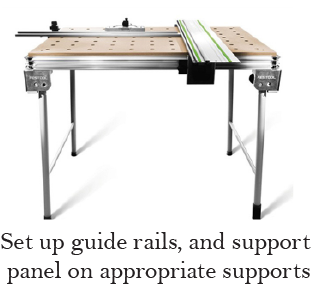
- 0:45 Pre-Fabrication Setup
- 1:10 General Cutting and Chamfering
- 2:07 Door & Window Detailing
- 2:32 Exposed Fastening Drilling
- 3:18 Concealed Fastening Drilling
- 4:12 Kerfing
- 4:40 Rabbeting
- 5:01 Penetrations
- 5:33 Final Inspection
|
|
Step 3: Prep Stage Continued
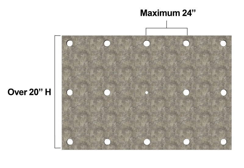
Fixed and floating point holes are required on every panel to allow for panel expansion and contraction
Support Points Per Panel
 |
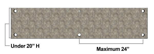 |
| Panels over 20”H require 3 rows of horizontal fasteners and a minimum of 3 vertical supports. |
Panels under 20”H require 2 rows of horizontal fasteners and a minimum of 3 vertical supports. |
Requirements
- Minimum of 3 supports, vertically and horizontally are required except for panels under 20”.
- Maximum space between fasteners 24”.
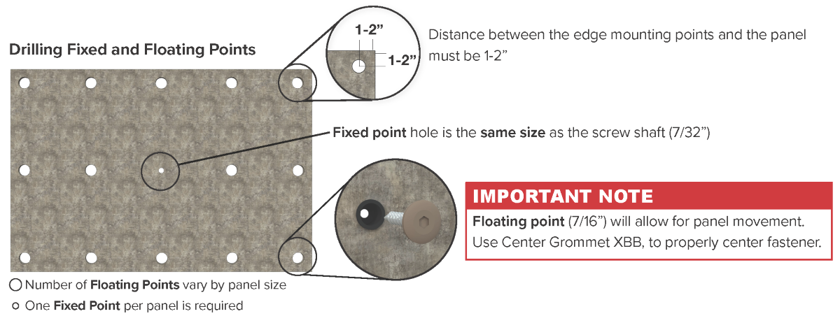
- Distance between the edge mounting points and the panel edges must be 1-2”.
- The actual number of fastening points and distance between supports must be verified by a building professional for wind load as per local building code.
Step 4: Panel Installation
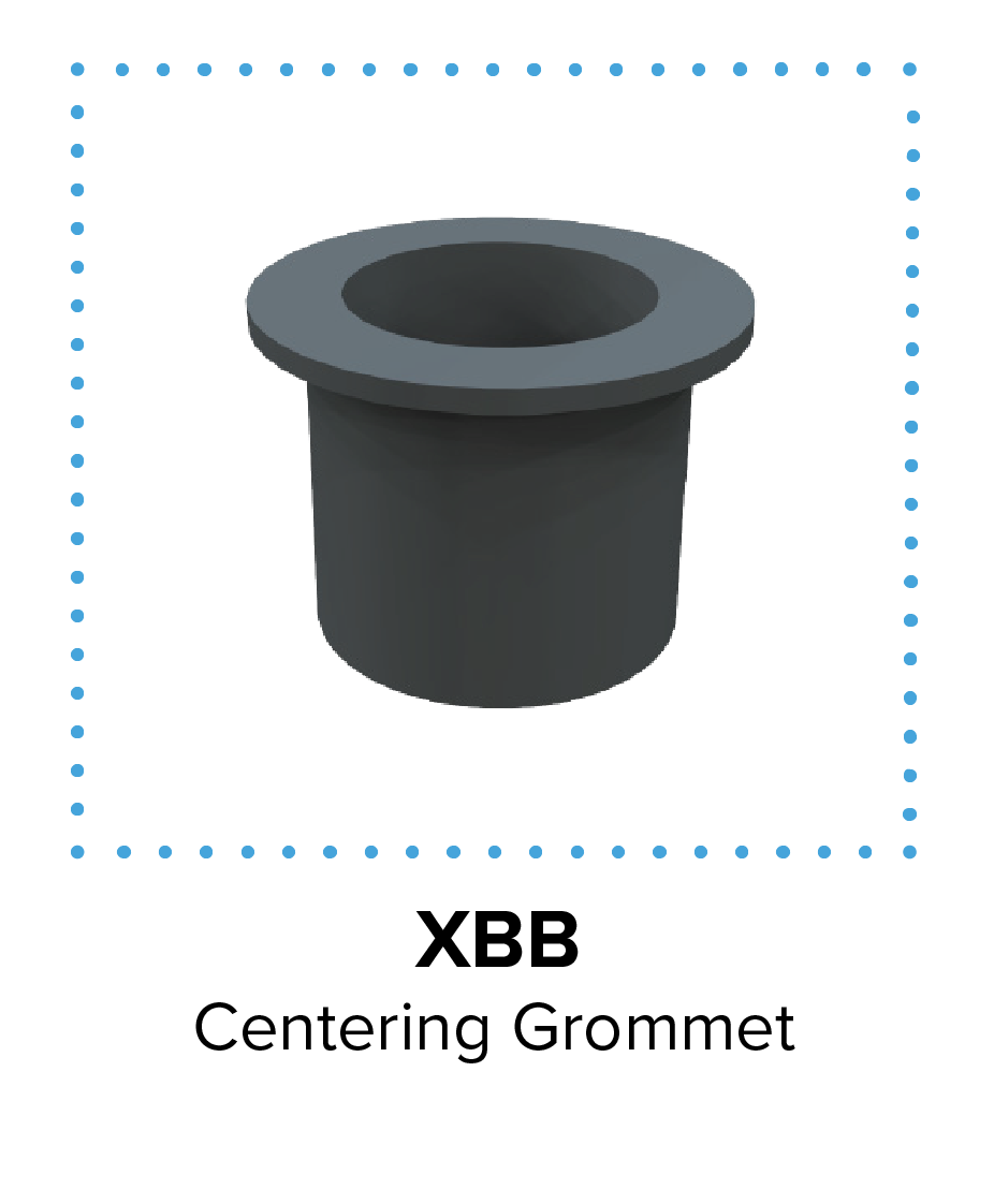
Position of Centering Grommet and Fastener
Insert the Centering Grommet, XBB, into the pre-drilled floating point hole. Insert Fastener SX3-D16 into the grommet centering hole. Tighten to min. 23 - max. 27 lb-in torque.
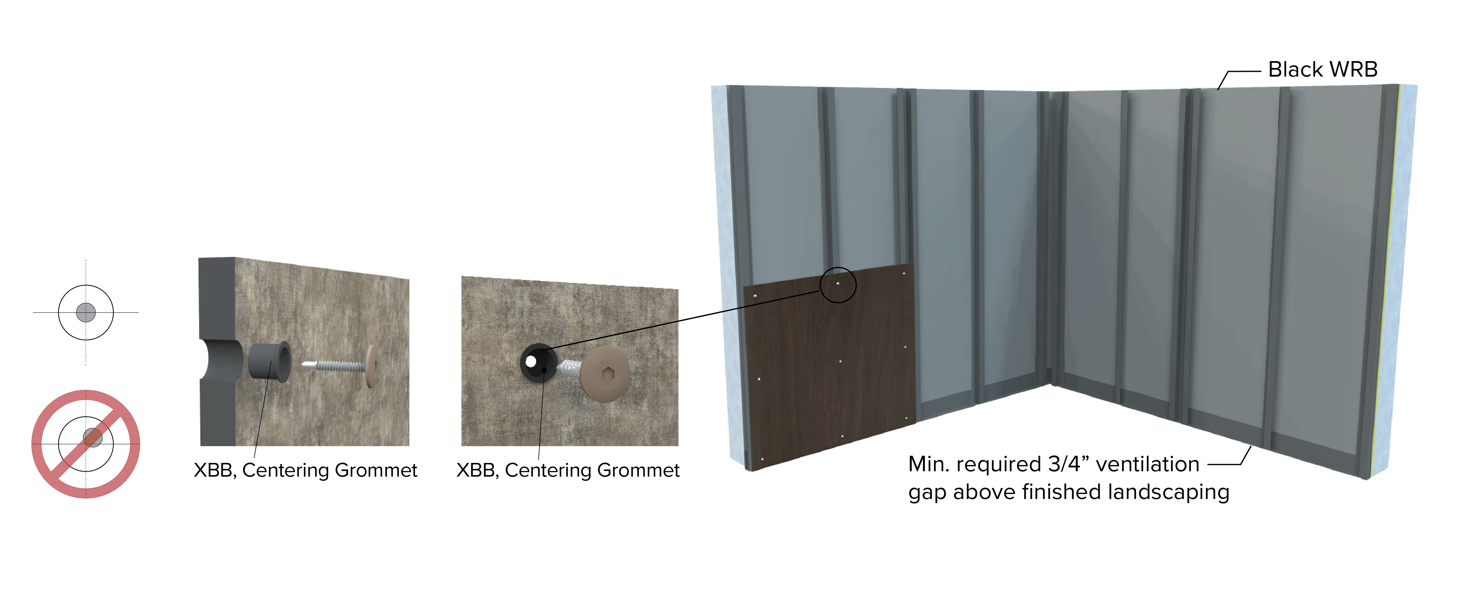
4a. Starting at the bottom of the wall install the first panel with one fixed point (7/32”) and the remaining floating points (7/16”) with an XBB Centering Grommet and SX3-D16 Fasteners.
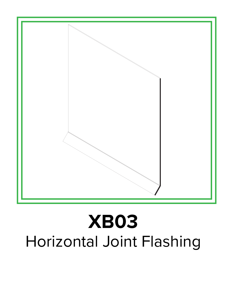
Step 5: XBO3 Placement
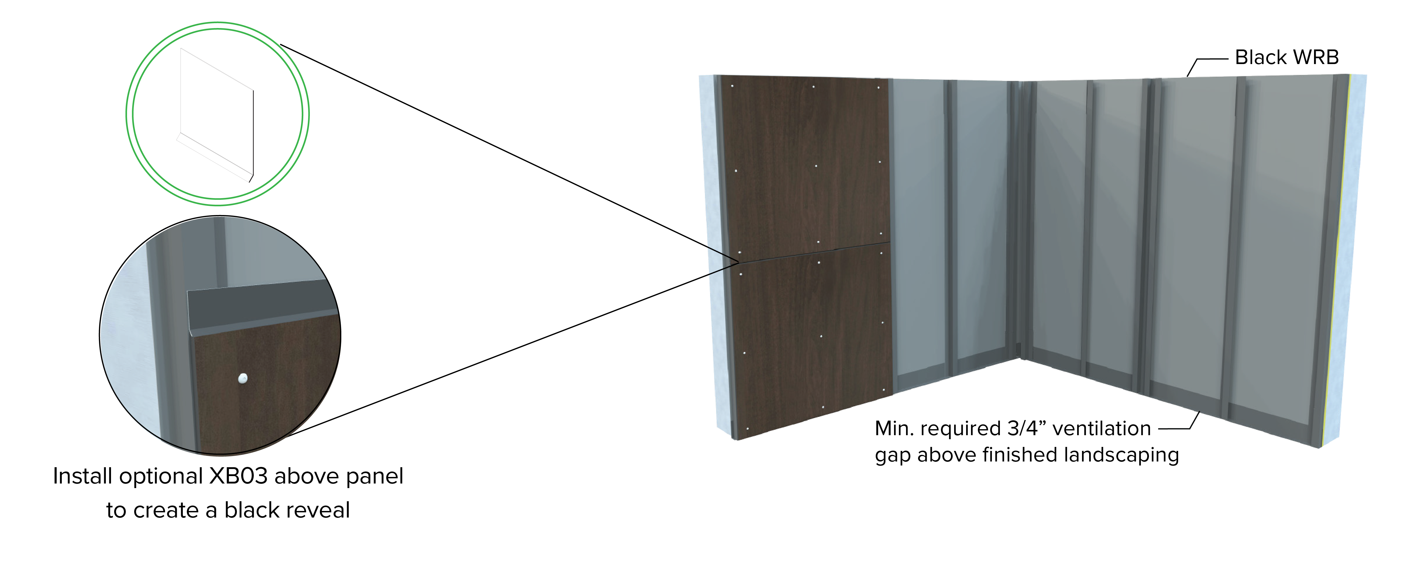
5a. Install the optional XB03 above panel with a small piece of tape to hold it in place.
5b. Place second panel above first panel and install with one fixed point (7/32”) and the remaining floating points (7/16”) with an XBB Centering Grommet and SX3-D16 Fasteners. Make sure there is a 3/8” gap between panels.
Note: SX3-D16 Fasteners go through the XB03 to secure in place.
Step 6: Continue Panel Installation
6a. Continue installing panels per steps 4 and 5 making sure to leave a 3/8” between panels.
6b. Installation should not allow for standing water to accumulate anywhere on the panel.
Step 7: Finished Wall
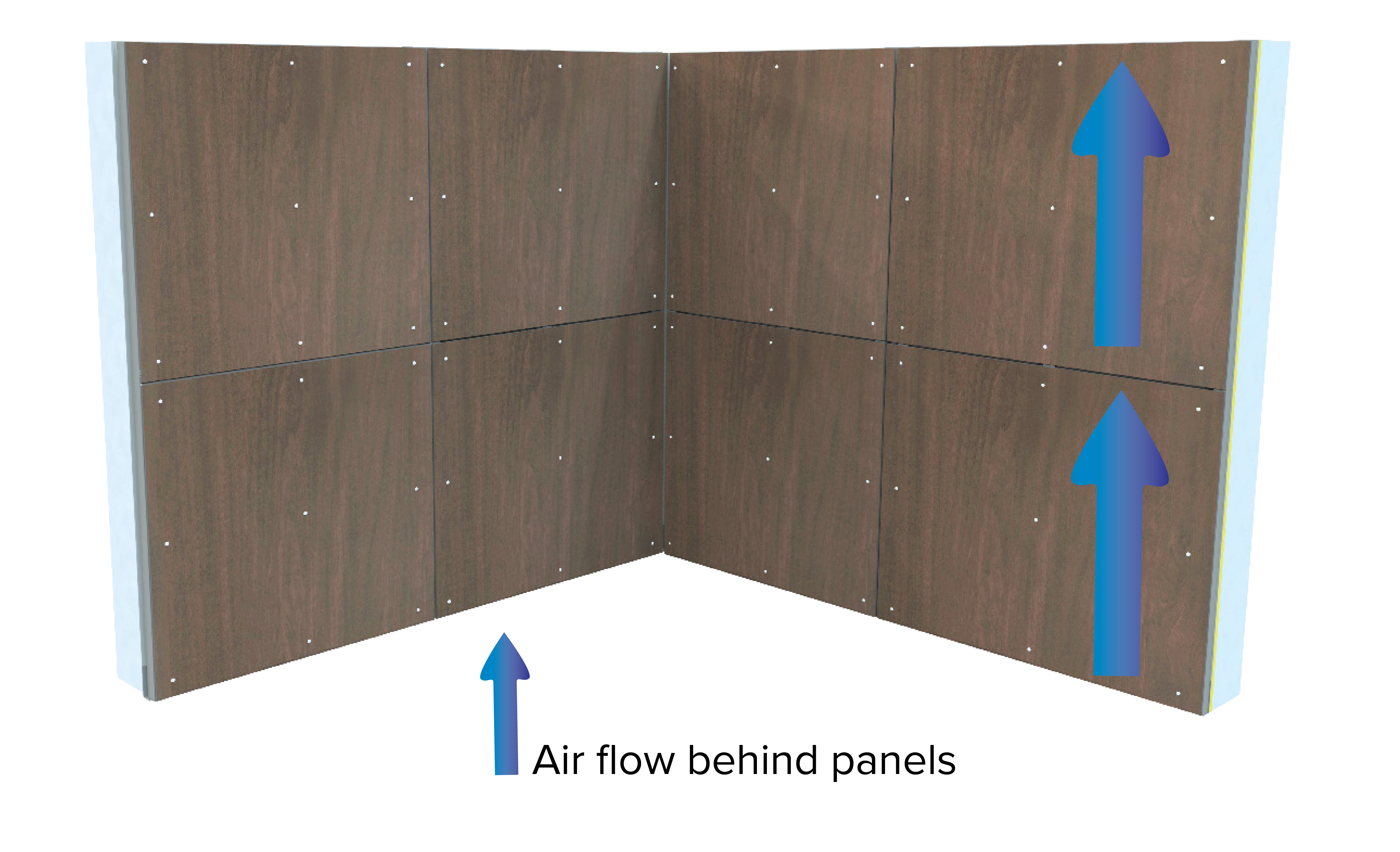
7a. The finished wall should have unobstructed continuous air flow for proper performance.
7b. Installation should not allow for standing water to accumulate anywhere on the panel.
Step 8: Completed Wall
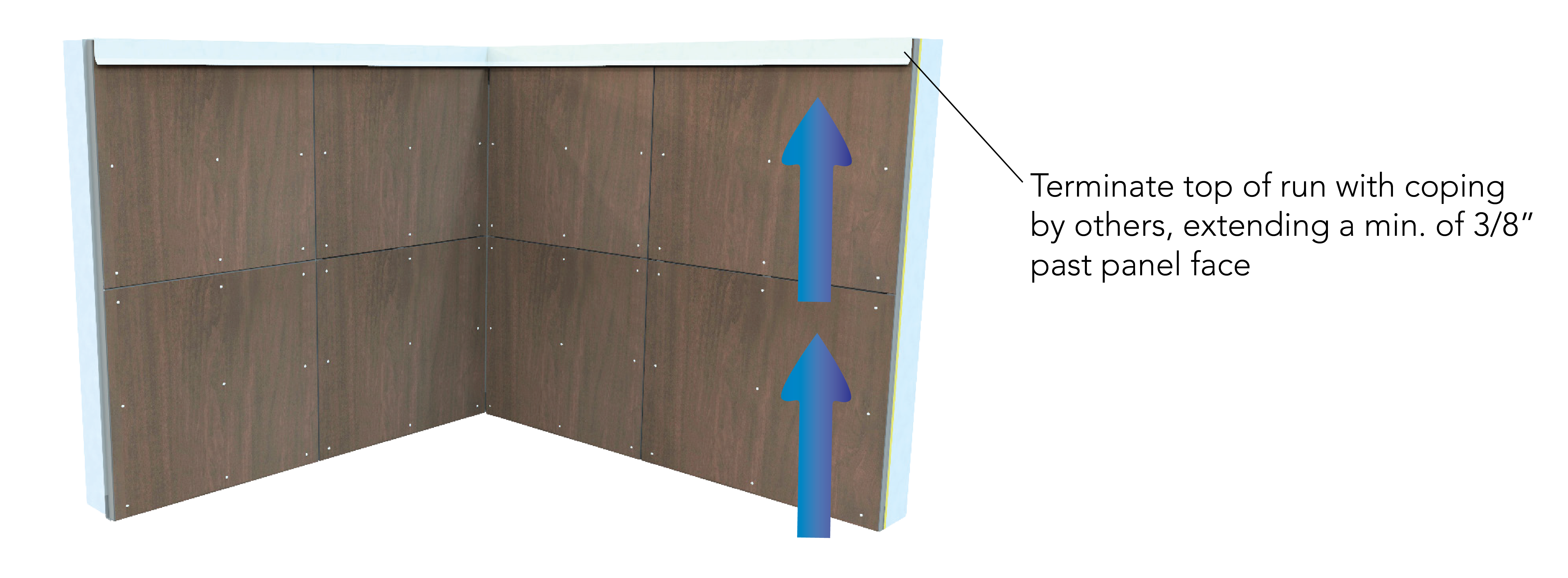
8a. Where required, terminate the top of runs with coping or flashing by others extending a minimum of 3/8” past the panel face.